Showing posts with label Digital Electronics - 2021-2022 Even Semester. Show all posts

Intel 8085 Microprocessor - Pin Configuration - Concise Notes For Exams


The pins of a 8085 microprocessor are classified into seven groups.

Address Bus :

A15-A8, it carries the most significant 8-bits of memory/IO address.

Data Bus :

AD7-AD0, it carries the least significant 8-bit address and data bus.

Control and Status Signals :

These signals are used to identify the nature of operation. There are 2control signal and 3 status signals.

Two control signals are RD, WR 

RD − This signal indicates that the selected IO or memory device is to be read and is ready for accepting data available on the data bus.

WR − This signal indicates that the data on the data bus is to be written into a selected memory or IO location.

Three status signals are IO/M, S0 and S1.

IO/M

This signal is used to differentiate between IO and Memory operations, i.e. when it is high indicates IO operation and when it is low then it indicates memory operation.

S1 and S0

These signals are used to identify the type of current operation.

Power Supply :

There are 2 power supply signals − VCC & VSS. VCC indicates +5v power supply and VSS indicates ground signal.

Clock Signals :

There are 3 clock signals, i.e. X1, X2, CLK OUT.

X1, X2 − A crystal (RC, LC N/W) is connected at these two pins and is used to set frequency of the internal clock generator. This frequency is internally divided by 2.

CLK OUT − This signal is used as the system clock for devices connected with the microprocessor.

Interrupts :

Interrupts are the signals generated by external devices to request the microprocessor to perform a task. There are 5 interrupt signals, i.e. TRAP, RST 7.5, RST 6.5, RST 5.5, and INTR. We will discuss interrupts in detail in interrupts section.

INTA − It is an interrupt acknowledgment signal.

RESET IN − This signal is used to reset the microprocessor by setting the program counter to zero.

RESET OUT − This signal is used to reset all the connected devices when the microprocessor is reset.

READY − This signal indicates that the device is ready to send or receive data. If READY is low, then the CPU has to wait for READY to go high.

HOLD − This signal indicates that another master is requesting the use of the address and data buses.

HLDA (HOLD Acknowledge) − It indicates that the CPU has received the HOLD request and it will relinquish the bus in the next clock cycle. HLDA is set to low after the HOLD signal is removed.

Serial I/O Signals :

There are 2 serial signals, i.e. SID and SOD and these signals are used for serial communication.

SOD (Serial output data line) − The output SOD is set/reset as specified by the SIM instruction.

SID (Serial input data line) − The data on this line is loaded into accumulator whenever a RIM instruction is executed.

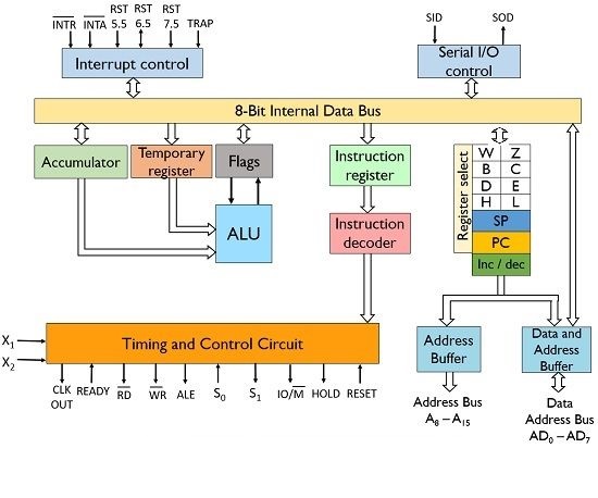
Intel 8085 Microprocessor - Internal Architecture - Concise Notes For Exams

Intel 8085 is an 8-bit microprocessor with a capacity to address 216 memory locations - 64 KB. It can perform 8-bit operations at a time. It needs a single 5 V power supply with a clock running at a frequency ~3 MHz .

Architecture of 8085 Microprocessor:

General Purpose Registers are a set of registers which are located inside the 8085 microprocessor. They can store and process 8 bit data. These registers are B,C,D,E,H and L. They can be combined to form pairs BC,DE and HL in order to enable the execution of 16-bit operations. 

General purpose registers are accessible to the programmer through the 8085 instruction set. They are used to insert and transfer data. 


Temporary Registers 

These registers are used by the ALU to store the data on temporary basis and these are not accessed by the programmer. These are of 2 types:

  1. Temporary data register – It is an 8-bit register that holds the operand and provides it to the ALU for program execution. Also, the immediate results are stored by the ALU in this register.
  2. W and Z register – These registers are also used to hold the temporary values. It is used by the control section of the microprocessor so as to store the data during operations.
Program Counter (PC) :

It is basically a special purpose register that is used to store the address of the memory location of the instruction to be performed. It is a 16-bit register as it stores address. 
It functions in such a way that it fetches the opcode from one memory location and simultaneously get incremented by the next memory location. Thus, it provides sequencing of the program to be executed.

Stack Pointer (SP) :

It is a 16-bit register and is a part of memory. The data is stored in the stack in serial format and stack pointer generally stores the address of the last data element stored in the stack. Thus the stack is based on LIFO.

Whenever a new data is added in the stack, then the stack pointer starts pointing towards the very next memory location. When a data element is removed from the stack, then the stack pointer points to previous occupied memory location.

Accumulator : 

It is an 8-bit register that stores the result of the operation performed by the ALU. It is  known as register A. 

Flags :

Flag register basically holds the status of the current result generated by the ALU and not the actually generated result. Thus we can say it is used to test the data conditions.

8085 has 5 flags that shows 5 different data conditions. These are carry, sign, zero, parity and auxiliary carry flags.


INTERNAL TEST I - ATOMIC AND NUCLEAR PHYSICS - 7BPH4C1


 I INTERNAL TEST - ATOMIC AND NUCLEAR PHYSICS - 7BPH4C1

TIME: 2 Hrs                                                                                                 TOTAL:  50 Marks


Part A - 5 x 2 = 10 Marks


1.Write any two properties of Positive Rays.

2.Define Critical Potential.

3.State the laws of Photo Electric Emission.

4.State Pauli's Exclusion Principle.

5.State Selections Rules for electronics transition in atoms.


Part B - 4 x 5 = 20 Marks


6. Describe the construction and working of Bainbridge Mass Spectrometer.

7. Derive Einstein's Photo Electric Equation.

8. Explain the various quantum numbers associated with the vector atom model.

9. Explain the Fine Structure of  Sodium D Lines.


Part C - 2 x 10 = 20 Marks


10. Describe the experimental determination of critical voltage by Frank and Hertz Experiment.

11. Describe the Stern-Gerlach Experiment.

II INTERNAL TEST - DIGITAL ELECTRONICS - 7BPH6C2

  II INTERNAL TEST - DIGITAL ELECTRONICS - 7BPH6C2


TIME: 2 Hrs                                                                  TOTAL:  40 Marks

Part A - 5 x 2 = 10 Marks

1. What is D Flip Flop?

2. Write note on resolution of ADC.

3. Expand ROM, RAM and PROM.

4. What is accumulator in 8085 μp?

5. What is the function of stack –pointer in Intel 8085?


Part B - 2 x 5 = 10 Marks

6. Explain the working of clocked RS –flip flop.

7. Describe the working of a binary ladder D/A converter.


Part C - 2 x 10 = 20 Marks

10. Explain the action of simultaneous conversion ADC .

11. Draw the pin-out diagram of 8085 μp.

I INTERNAL TEST - DIGITAL ELECTRONICS - 7BPH6C2

 I INTERNAL TEST - DIGITAL ELECTRONICS - 7BPH6C2


TIME: 2 Hrs                                                                 TOTAL:  50 Marks

Part A - 5 x 2 = 10 Marks

1. Convert 10234 in decimal into hexadecimal.

2. Express decimal number 6754 in BCD.

3. Write first 10 Gray code numbers in order.

4. Simplify the Boolean expression Y = A(A+B)

5. What's the difference between a truth table and a Karnaugh map?


Part B - 4 x 5 = 20 Marks

6. State and Prove Demorgan's Theorems.

7. Give the Symbols and Truth Tables for XOR and XNOR gates.

8. How Half Adder adds two bits at a time? Explain with truth table.

9. Simplify Y = ∑m(10,11,12,13,14,15) using K-Map method.


Part C - 2 x 10 = 20 Marks

10. Explain how NOR gate can be used as a universal building block.

11. Simplify using K-Map Y = f(A,B,C,D) = ∑m(1,3,7,11,15) + ∑d(0,2,5,8)

Digital Electronics - 7BPH6C2 - Syllabus


III YEAR – VI SEMESTER
COURSE CODE: 7BPH6C2

CORE COURSE XIV – DIGITAL ELECTRONICS

Unit I              FUNDAMENTALS
Codes and Number Systems–Decimal, Binary, Octal and Hexadecimal number systems–Inter conversions–8421BCD code–Other 4 bit BCD codes–Excess 3 code–Graycode

Basic LOGIC gates – AND, OR, NOT, NAND, EX-OR functions – their truth tables.  NAND & NOR as Universal gates – De Morgan's theorem – Boolean Algebra - associative law, commutative law and distributive law.

Unit II             COMBINATIONAL LOGIC
Binary Arithmetic Circuits – Half Adder – Full Adder– 8421 BCD Adder – Half Subtractor – Full Subtractor.

Simplification of Boolean functions – algebraic simplification – AND-OR logic – NAND-NAND net work – OR – AND logic – NOR-NOR network – Sum of Products & Product of Sums – Karnaugh mapping of two, three, four variables – Don't care conditions

Unit III           SEQUENTIAL LOGIC
Flip-Flop – R-S Flip-Flop – Clocked R-S Flip-Flop – D Flip-Flop- J-K Flip-Flop. 

Registers & Counters : Registers – Shift Registers – Shift Right, Shift Left Registers – Counters – Ring counter – Asynchronous (Ripple) Counter – Mod 10 counter – up counter – down counter – Synchronous Counter – Different modulli Counters.

Unit IV           D/A AND A/D CONVERTERS
Introduction – Variable resistor network – Binary ladder – D/A Converter – D/A accuracy and resolution

A/D converter : Simultaneous conversion – counter method – successive approximation – A/D accuracy and resolution.

Unit V             MEMORY CIRCUITS AND MICROPROCESSORS
Programming bipolar PROMS – MOS static RAM cell – MOS dynamic RAM cell.

Microprocessors: Introduction to microprocessor - internal architecture of Intel 8085 microprocessor - Block diagram – Registers - internal Bus organization- functional details of 8085 IC pins and Control signals. 

Text Books:
1.       Integrated Electronics Millman and Halkias, International Ed., McGraw Book Co., New Delhi, 1972.
2.       Digital Principles and Application – Malvino and Leach, , 4th Ed., Tata McGraw Hill,  VI Edn, New Delhi, 2008.
3.       Fundamentals of Digital Electronics and Microprocessor– Anokh Singh and A.K. Chabra, , S.Chand and Co Ltd, II Edn., New Delhi, 2005.

Books for Reference:
1.       Digital Technology Principle and Practice – Virendra Kumar,  New Age International Pvt. Ltd., New Delhi, 2005.
2.       Digital Fundamentals – Floyd and Jain, Pearson Edn. Singapore, 2006
3.       Digital Circuits and Logic Design – Samuel.C.Lee, Prentice Hall of India Pvt.Ltd, New Delhi, 2005