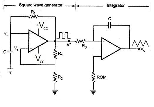
A triangular wave generator using op-amps can be realized by cascading the output of an op-amp square wave generator to the input of an active integrator. Such an implementation is shown in the following circuit diagram.
 |
| Triangular Wave Generator |
Working and Circuit Analysis
Here the first op-amp is wired up as a comparator at the non-inverting input. If V+ is greater than V- then the output voltage V' will swing to +Vcc and to -Vcc if V+ is less than V- . When the circuit is switched on assume the output voltage is +Vcc and the capacitor C begins charging through the feedback resistor R with the time constant RC. As a result V- increases with time and when it becomes greater than V+ the output voltage swings to the negative rail voltage -Vcc. Now the capacitor is is discharged through R. When the voltage becomes less than -Vcc the output voltage swings back to +Vcc and the cycle begins again generating square wave.
The output of square wave generator V' is fed into the inverting input of second op-amp wired as an active integrator through the resistance R3 .
A triangular wave is generated when a capacitor is charged and discharged by a constant current source. Let V' be hight at +Vcc. This causes a constant current +Vcc/R3 through C in the integrator part to drive Vout negative linearly. When V' is low at -Vcc it forces a constant current -Vcc/R3 through C to drive Vout positive linearly. The frequency of the triangular wave is same as that of square wave and given by,
 for the special case R1 = R2.
The output of square wave generator V' is fed into the inverting input of second op-amp wired as an active integrator through the resistance R3 .
A triangular wave is generated when a capacitor is charged and discharged by a constant current source. Let V' be hight at +Vcc. This causes a constant current +Vcc/R3 through C in the integrator part to drive Vout negative linearly. When V' is low at -Vcc it forces a constant current -Vcc/R3 through C to drive Vout positive linearly. The frequency of the triangular wave is same as that of square wave and given by,
